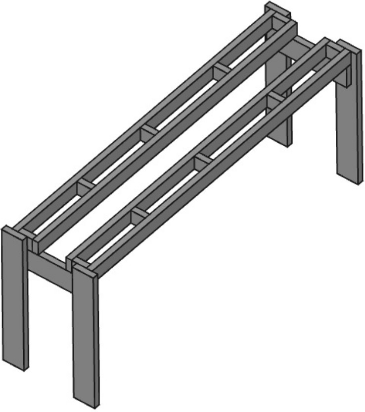
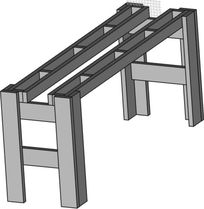
Project 8: Create a 8 foot long Work Table.
2018-04-21
Objective:
To economically build a 2' X 8' work table. The frame is constructed out of 2x4s and 2x6s and the top is 3/4" Red Oak Plywood. The intent is for a durable table that has utility to handle any home project. All tools used in this project are corded, they cost less and likely are more powerful. Only hand tools used build this work table. Do not require any special wood working tools, allows table to be fabricated in any garage. Creating dowel joints with hand drill is not easy, and I did struggle making holes straight but I was able to construct table as per design.
The main beams are constructed to accept the bolting pattern of a typical 6" shop vise (i.e. 5.35" 4-hole pattern).
Structure Detail and Overall Dimensions:
3 ft High X 2 ft Wide X 8 ft Long
Mass ranges from 125 to 150 lbs
Capacity 725 lbs vertical load anywhere on the table top.
Materials:
1. 4x 2" X 4" X 8' SYP Lumber. Cost $3.98 ea.
2. 4x 2" X 6" X 8' SYP Lumber. Cost $4.42 ea. 3. 1x 3/4" X 24" X 48" Plywood. Cost $26.49 ea. 4. 4x 36" Threaded Rod 1/4-20 UNC. Cost $1.97 ea. 5. 32x 1/4-20 UNC Nuts. Cost $1.75 all 6. 32x 1/4 Washers. Cost $1.45 all 7. 32x E-Z Lok Knife Edge Threaded Insert PN 400-4. Cost $0.50 ea. 8. 8x 3/8-16 UNC Bolt 4" Lg., $0.44 ea. 9. 16x 3/8 Washer, 0.24 ea. 10. 8x 3/8 Nut, 0.10 ea. 11. 10x #10 2" Wood Screws. Cost $0.12 ea. 12. 4x 3/8" X 36" Oak Dowels. Cost $1.56 ea. 13. Wood Glue. Cost $1.00 14. Oil Based Primer. Cost $5.00. 15. Oil Based Paint. Cost $5.00. 16. Tool wear and tear, sand paper other consumables, Cost $10 all. Total cost of all materials used $115 USD.Tools:
1. Makita 7 1/4 Circular Saw, est. cost $100 2. Makita 4 1/2 Angle Grinder, est. cost $69 3. Makita Orbiting Sander 5.0" VSP, est. cost $79 4. Ryobi Jig Saw, est. cost $69 5. 3/8 Drill, corded, est. cost $50 6. 6-Pc. Brad Point Drill Bit Set, est. cost $15 7. Black Oxide Drill bit Set (29-Piece). est. cost $27 8. 6-Pc. Spade Bit Set, est. cost $10 9. 2x 4in C-Clamps., est. cost $12 ea. 10. 4x 8in C-Clamps., est. cost $15 ea. 11. Ratchet Wrench 3/8, est. cost $13 12. 7/16 socket, est. cost $2 13. 7/16 wrench, est. cost $3 14. 9/16 socket, est. cost $3 15. 9/16 wrench, est. cost $4 16. Aluminum Speed Square, est. cost $8 17. 25' Tape Measure, est. cost $10 18. 18" Stiff Ruler, est. cost $8 19. Screw Driver Interchangeable Set, est. cost $7 20. Screw Driver 3/8 X 8", est. cost $8 21. 9" polycast torpedo level, est. cost $3 22. 48" Johnson structo-cast level, est. cost $ 9.98 23. Wood Chisel, est. cost $5 24. 8 in. Slip Ring Pliers, est. cost $9.97 25. 8 in. Long Nose Pliers, est. cost $ 5.17 26. 4.5" X 0.045" Cut Wheel, $2.75 27. Purdy 2.5" White Bristle 100% Natural, soft, est. cost 14.47 28. 2" Putty Knife, est. cost $7.97 29. Safety Knife, est. cost $6.98 30. Paint Spinner, $9 31. EZ-Lok, Drive Tool, 500-3, est. cost $9.50 Total cost of all tools if all bought new for project is approximately $675 USD.Design:
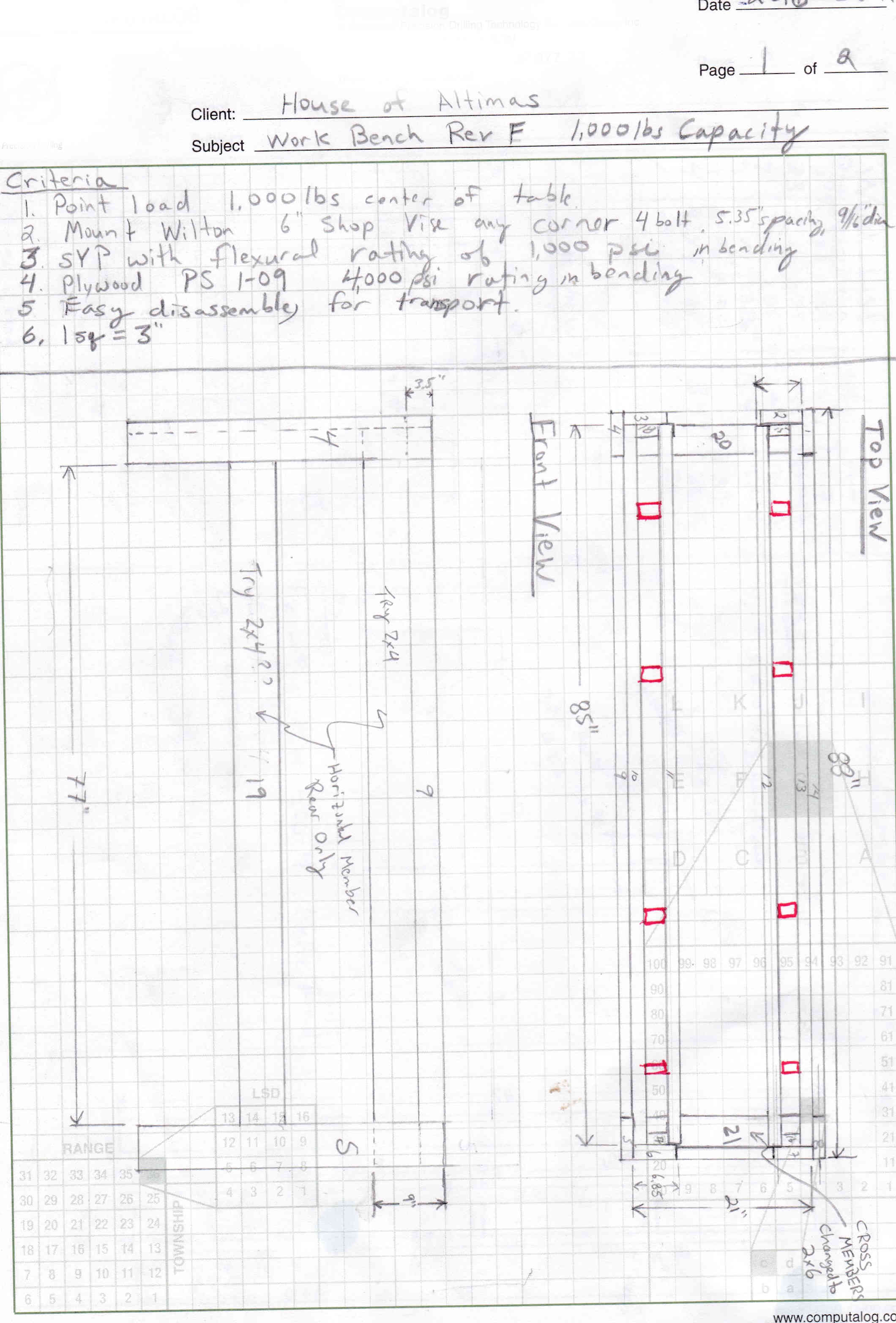
Note 1: Used Southern Yellow Pine (SYP), #2 Prime Lumber.
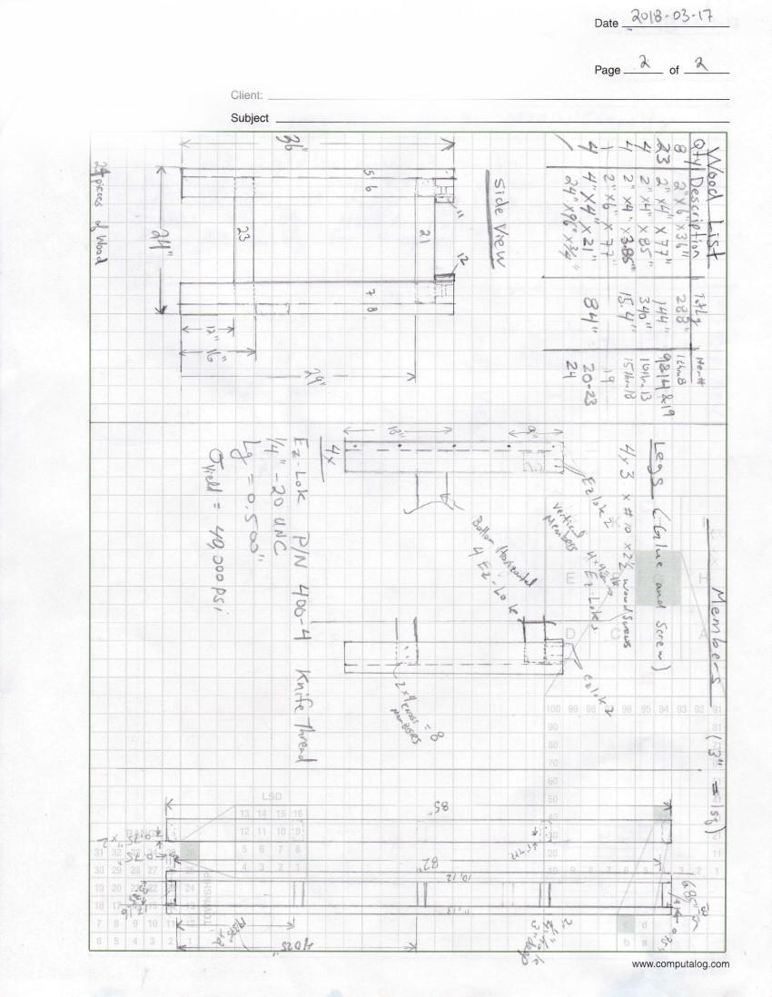
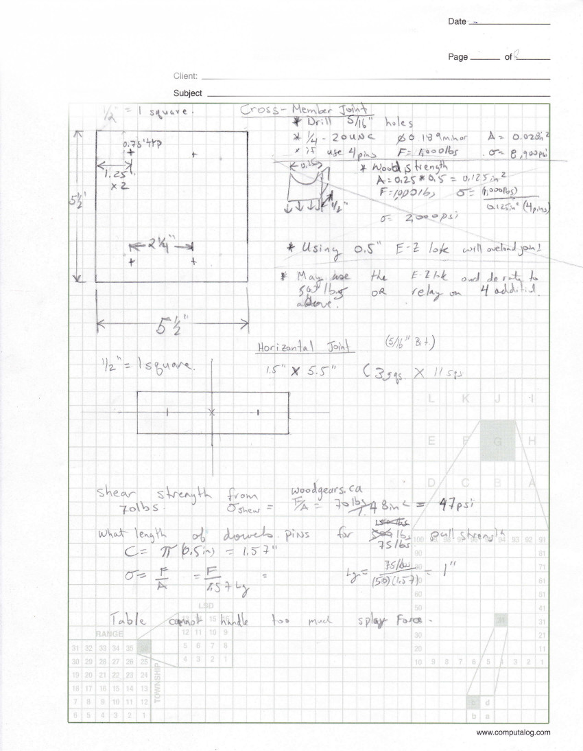
Note 2: To estimate strength of wood dowel joints I referenced www.woodgears.ca.
Note 3: I decided to use E-Z Lok knife thread inserts. I used a screw driver to install and this turned out to be an error because the taper placed a high corner load on the E-Z Lok insert resulting in broken corners. Also, the inserts did not seat straight. I will purchase the E-Z Lok tool next time I try this.
Note 4: For wood screw pre drill pilot, shank, and c'bore sizes.
Note 5: This design was created manually using graph paper. However, free CAD tools could be used to do this. I tried using FreeCAD. With this software I was able to get an accurate solid model but the drawing tools were not user friendly. I gave up after several hours trying to produce manufacturing drawings. Posted are graphics of this work.
FreeCAD:
Procedure
1. Cut all 2X 6 lumber to length:
2. Cut all 2 X 4 lumber to length:
3. Cut Red Oak plywood to size.
*Steps 4 to 11 assembly the legs
4. Cut twenty pieces of 3/8 in. diameter oak dowel by 2.5 in. long each. These dowels will be used to assembly the vertical legs.
5. Orient the front 2x6 on the work bench so 1.5 in. is protruding from the edge and clamp with two 4 in. C-clamps.
6. Mark the 5 dowel locations with pencil using tape measure and speed square.
7. Clamp the side 2x6 to the front 2x6 using two 8 in. C-clamps.
8. Drill holes to a 2.5 in. depth using a 25/64 in. drill bit.
9. Apply glue to hole, and brush glue on dowel. Then drive dowel into hole. Repeat this 5 times.
10. Allow the glue to set for 30 minutes then remove clamps. Set the leg aside to dry for 24 hours.
11. Repeat steps 4 to 10 for the remaining three legs.
12. Prime the legs, bottom end and 1/3 up leg. Cover areas that will be difficult when applying final paint.
13. Cut 16 pieces of 2.5 in. long 1/4-20 UNC threaded rod.
14. Mark location for upper and lower horizontal members with two legs on table. Clamp the top horizontal member in place and check geometry.
15. Mark out centers for 4 holes of the eccentrically loaded bolted connection. Refer to the 3rd scanned page under title "Cross Member Joint" for geometry.
16. Drill eight (four each side) 2" deep holes using 25/64 drill bit.
17. Remove clamps and horizontal member.
18. Thread in the E-Z Lok Knife Edge Threaded Insert (PN 400-4) in eight places.
19. Thread in 8 pieces of the 1/4-20 UNC threaded rod. Due to not using EZ-Lok tool several inserts were not aligned. In one case the threaded rod had to be bent with two pliers in order to assemble.
20. Fit the horizontal member onto the legs. Then place 1/4 washers and 1/4-20 UNC nuts. Tighten each rod using a socket to about 75 in·lbs.
21. Repeat steps 14 to 20 for the other support.
22. Cut 40 pieces of 2.0" long 3/8 Oak Dowel.
23. Lay out one 85" long 2x4 on a work table. Orient the five 3.85" spacers, and rest a second 85" 2x4 on top. Once orientation is correct, check the geometry. Spread glued on beam and spacer face then clamp to work table between the spacers. If do not have enough clamps allow glue to set for 30 minutes before continuing.
24. Repeat step 23 for the top 2x4 main beam.
25. Mark centers of the dowel pins in 10 locations. Refer to the 3rd scanned page under title "Horizontal Joint" for geometry.
26. Drill 2.5" deep in 10 places using a 25/64 drill bit.
27. Apply glue to hole, and brush glue on dowel. Then drive dowel into hole. Repeat this 10 times.
28. Allow the glue to set for 30 minutes then remove clamps.
29. Flip the beam, and repeat steps 25 to 28.
30. Set the leg aside to dry for 24 hours.
31. Stand up the two vertical supports about 85" apart. Balance the two main beams on top.
32. Clamp the table together at the four corners. Make all measurements and unclamp as necessary to make adjustments. Check level of the beams, if not to satisfaction shim the main beams (i.e. the table top rests only on the main beams).
33. Starting at one corner mark out 2 hole centers. 1" and 2.5" from top 1.5" from inside front edge. Repeat process for other 3 corners.
34. Drill through the front vertical 2X6 and the main beam 2x4. Insert 3/8-12 UNC bolt with washer and tap in with hammer if necessary. Place washer on back and thread on nut. Torque each bolt to 100 in·lbs. Repeat process for other 3 corners.
35. Paint as desired.
36. Using 48" level check main beam is always highest, nothing should protrude above main beam. If so use orbiting sander to level.
37. Place oak plywood top and align as necessary.
38. Measure and mark centers at 5 locations along front 2.25" from the edge, at 12", 30", 48", 66", and 84". Repeat for the back edge.
39. Drill 2" holes using a 1/8" straight pilot drill. Then drill 3/4" long 13/64" for the shank, and follow up with a 27/64" for the counter sink.
40. Screw in the ten wood screws using the power drill.
41. Unit likely will not fit through the door so unscrew table top and remove the main beams. Move support assembly near it’s final installation location and reassembly. Can eliminate this step by moving near final location after paint (step 25).

