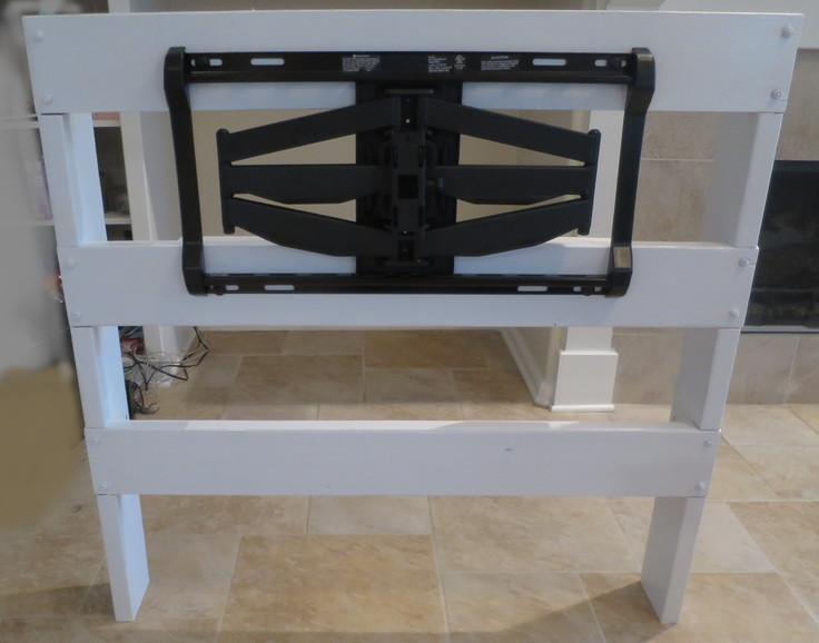
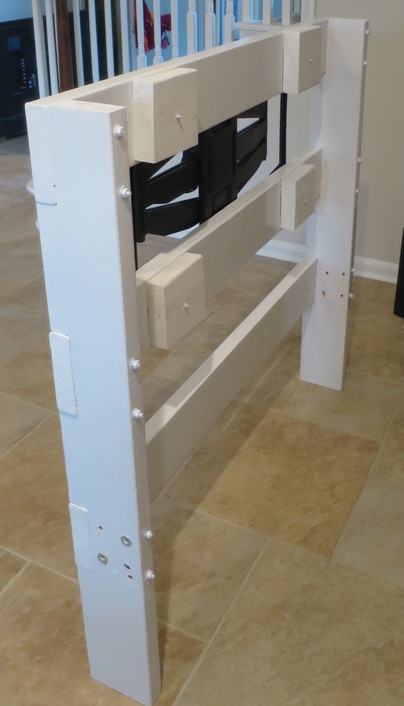
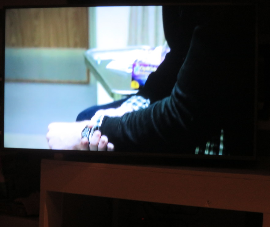
Project 7: Create a self supporting TV stand.
2018-03-15
Objective:
To economically build a self supporting TV stand.
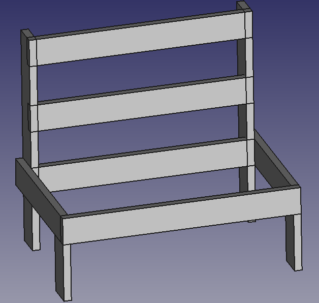
For anyone who set-up a LED/LCD TV using the included stand knows it may not position to location in mind, and in general it is difficult once in place to add or remove cables. I intended to remedy this by using a full-motion TV wall mount. However, drilling into the wall was not appetizing so I decided to build a self supporting TV stand of my own design.
Only hand tools were used to build this stand. It works well but next time I would build 4 inches higher to position TV modestly higher.
Structure:
44 in. High
30 in. Deep
48 in. Wide
100 lbs Mass
250 lbs Capacity, mass extended 24" from top members.
Materials:
1. Sanus Full Motion TV Wall Mount, Model SLF9-B1. Cost $90
2. 4x 2" X 6" X 8' Southern Yellow Pine (SYP) Lumber. Cost $3.98 ea. 3. 3/4" X 30" X 48" Plywood. Cost $33 ea. 4. 3x 36" Threaded Rod 1/4-20 UNC. Cost $1.97 ea. 5. 20x 1/4-20 UNC Nuts. Cost $1.08 all 6. 20x 1/4 Washers. Cost $1.08 all 7. 10x #10 2" Wood Screws. Cost $0.80 all. 8. 4x 3/8" X 3" Oak Dowels. Cost $0.80 all. 9. Wood Glue. Cost $0.25 10. Oil Based Primer. Cost $4.00. 11. Oil Based Paint. Cost $4.00. Total cost of all materials used $157 USD.Tools:
1. Makita 7 1/4 Circular Saw 2. Makita 4 1/2 Angle Grinder 3. Ryobi Jig Saw 4. 3/8 Drill, corded 5. Drill Bit Set 6. 2x 4 in. C-Clamps. 7. 2x 8 in. C-Clamps. 8. Ratchet Wrench 9. 7/16 socket 10. 7/16 wrench 11. Aluminum Speed Square 12. Screw Drivers 13. Wood Chisel 14. Sand Paper, misc 15. 4.5" X 0.045" Cut Wheel Total cost of all tools if all bought new for project is approximately $400 USD.Design:
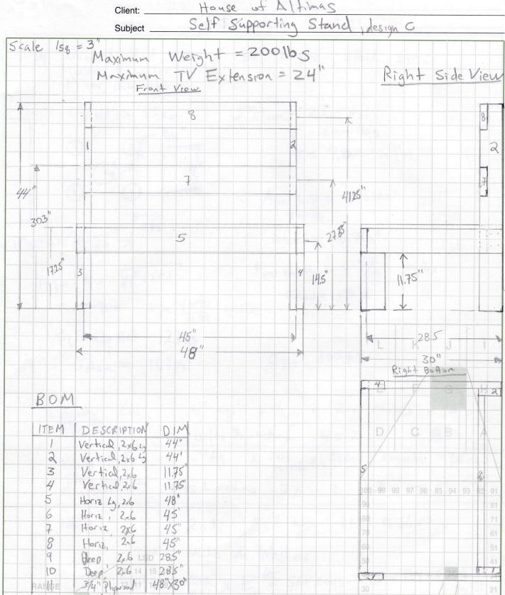
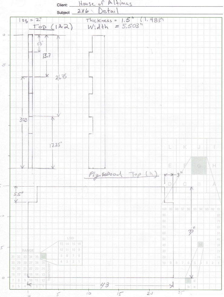
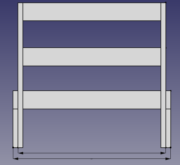
Note 1: The joining of the 3 45 in. cross members to the 2 vertical members are using 1/4 threaded rod, two spaced centered and 4 in. apart. Total of 12 1/4 X 6.5" rods required. Found you want rod extending about 1/2 each side for washer and nut.
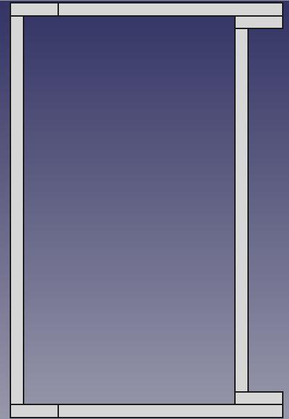
Note 2: The joining 2 28.5 in horizontal support members to the 2 vertical members are using 1/4 threaded rod, four spaced centered 4 in. apart vertically and 2.5 in. apart horizontally. This joint is important to react the torque from the TV support arm. IMPORTANT, rod is already extending through the bottom cross member. Make sure that new holes for the horizontal members do not intersect the installed rods from the cross-member. If design was revised this joint would be modified.
Note 3: As an alternate the last cross-member 48 in. long can be screwed to the two 28.5 in. horizontal members using #10 X 2.5 in. wood screws.
Note 4: The 2 11.75 in. vertical legs are connected to the 28.5 in. horizontal members using 3/8 oak dowels.
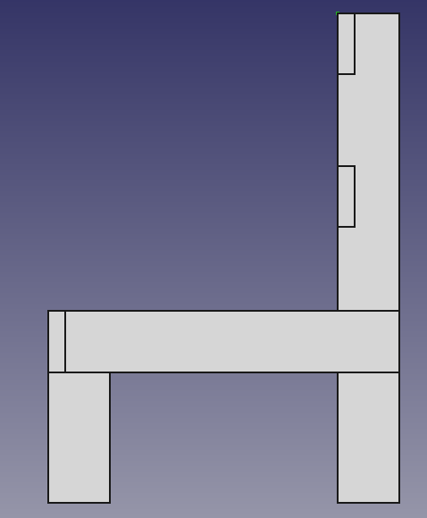
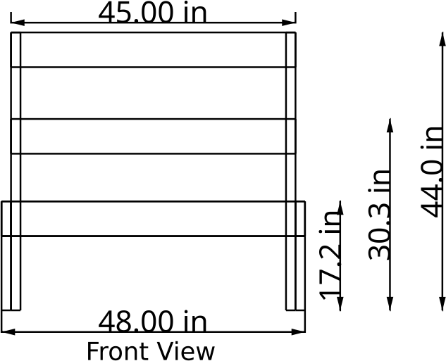
Note 5: This design was created manually using graph paper. However, free CAD tools could be used to do this. I tried using FreeCAD. With this software I was able to get an accurate solid model but the drawing tools were not user friendly. I gave up after several hours trying to produce manufacturing drawings. Posted are graphics of this work.
FreeCAD:
Procedure
1. Cut all 2X 6 lumber to length:1x 48 in. long
3x 45 in. long
2x 44 in. long
2x 28.5 in. long
2x 11.75 in. long
2. Cut 3 notches into the width of the 44 in. To do this set the cutting depth on circular saw to 1.5", the width of a 2X6, then mark out 5.5" for the notch. Then do many cuts over the width of notch, this leaves many thin sections. Remove thin sections of wood using a hammer and then chisel flat. Do this for all 6 notches in both vertical members.
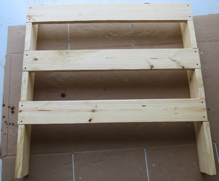
3. Lay the vertical beams, notches facing up, on the shop floor. Fit the three cross members into the notches. Measure and ensure the layout is as desired. Mark-out and drill holes for the 1/4-20 UNC rod. I used a 5/16 in. Titanium (coated in titanium ceramic) Pilot-Point Drill Bit for plenty of clearance. I drilled the cross-members and vertical members separately using a Black & Decker hand drill. Take your time as it is not hard to drill off target.
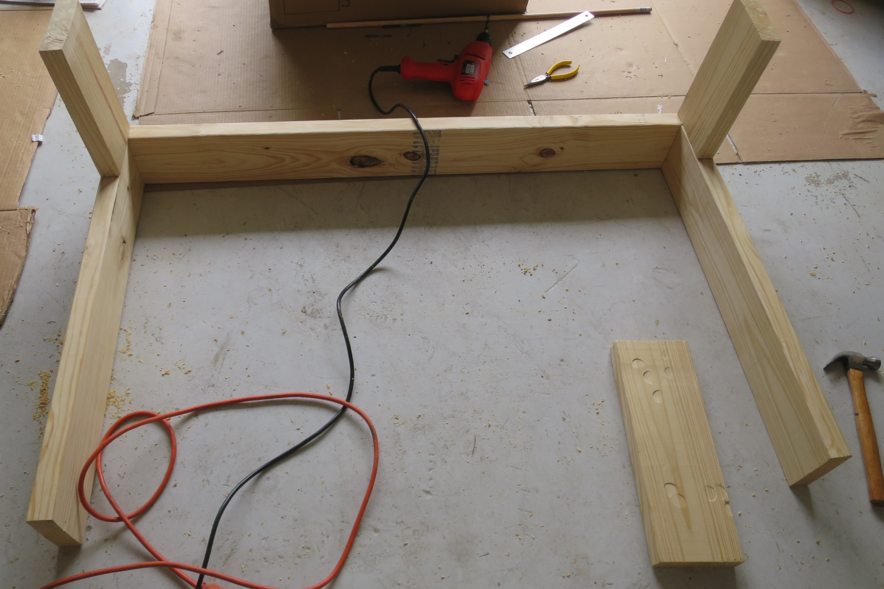
5. First cut 4 3/8" wood dowels 3 in. long. Stand the two 28.5 in. long horizontal members on shop floor. Place the 48 in cross member on the two horizontal members and ensure it is square. Drill two 7/16" diameter holes, each side, to 3.125" depth through the cross member into the horizontal members. Center holes to horizontal members and space 1" from top, and 2" between two pins, this leaves enough wood for the leg dowel pins. Apply glue to the 4 holes. Hammer the dowels in place and check to make sure structure is square. Let dry for 12 hours.
6. First cut 6 3/8" wood dowels 3 in. long. Drill three 7/16" diameter holes to 1.5" depth, one should be in the cross-member and two in the horizontal members. Mirror the holes on the face of each of the two legs. Apply glue to the holes in one leg and fit three dowel pins. Apply glue to the holes in cross and horizontal members and fit to the leg dowels. Ensure tight fit and square. Repeat for the other leg.
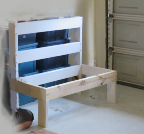
9. Install Sanus TV bracket to the TV of your choice.
13. Move to final position. Insert TV to the support base. Insert the lock screw and tighten hand tight. Loosen top and bottom rotation screws, level, and retighten.
14. Add sound system, and use Sanus's cable management shrouds.
Conclusion
Time to enjoy.

