Project 5: Verfication testing, of Optical Rotary Encoder.
2017-10-22
Objective:
To demonstrate basic functionality of an optical position rotary encoder.
The project is a repost of:
Link to Electro Schematics Optical Rotary Encoder article.
The web article was article written by T.K. Hareenden. Refer to his article for technical information. Intent here is to get the sensor tested so I can begin next step to program RPM sensorThis project uses code compiled from the Arduino IDE. Use at your own risk.
Materials:
1. Raspberry Pi Model B loaded with Raspbian loaded set-up with Keyboard and mouse.
2. Arduino Uno connected by USB cable to Raspberry Pi.
3. 3M Breadboard Solderless ACE309
4. Optical rotary encoder commonly used in printers.
5. Encoder Index Disc, or piece of plastic. Motor to drive encoder disc is optional.
6. 5 mm green LED
7. 220Ω, and 10kΩ resistor
8. Misc. 22AWG Jumper Wires
Software:
1. Linux OS - used Raspbian2. Arduino IDE 2.1 - GUI provied by Arduino to upload instructions to microcontroller
Hardware Set-Up, Compiling, and Testing:
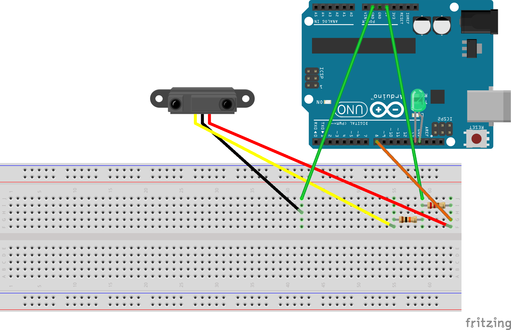
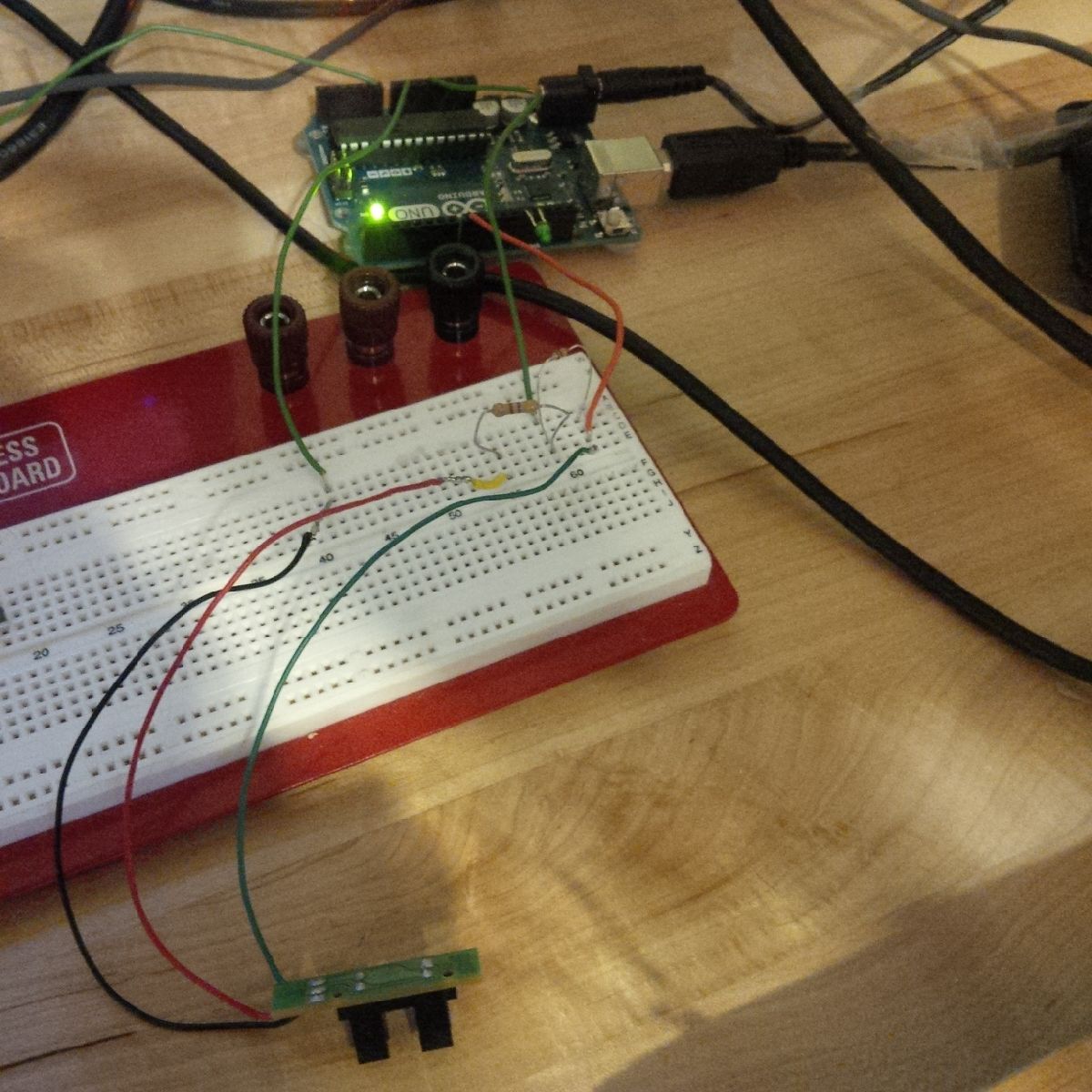
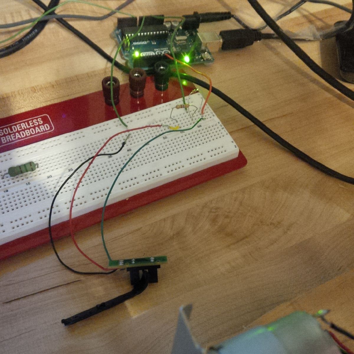
1. Simply plug in circuit as per diagram.


